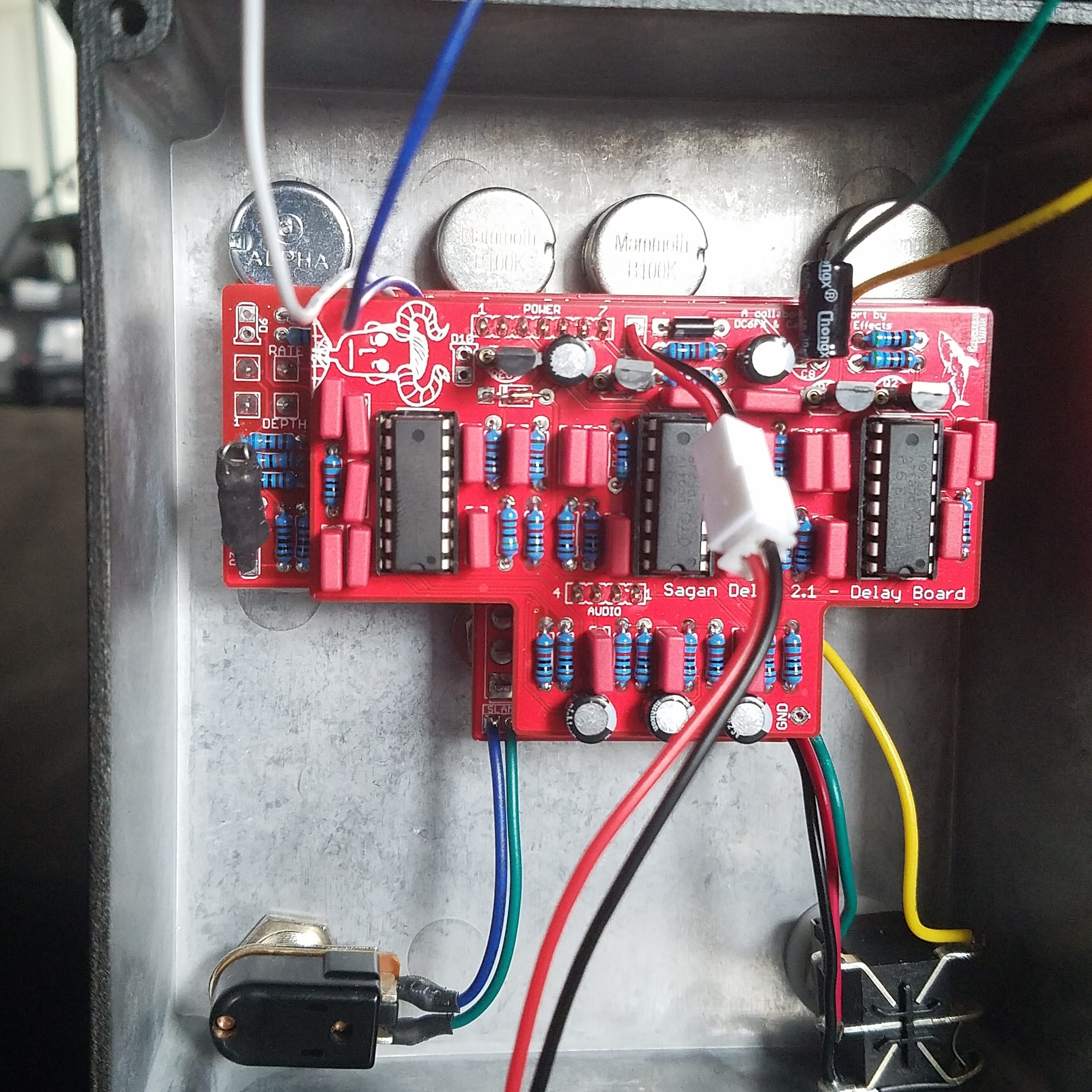
This was a challenging build and there are some things that are confusing. One thing I had trouble with is the sourcing of parts. Well the transistors. There are 3 different varieties of BC550, and I was unsure if I shoud use BC550B or BC550C. It is not spelled out in the docs. I had to ask on the Facebook group. There is also an LED on the PT2399 board that is optional but there is no indicating why it is optional. Is it an indicator or does it have an effect on the circuit. From what I remember it helps clean up the repeats.
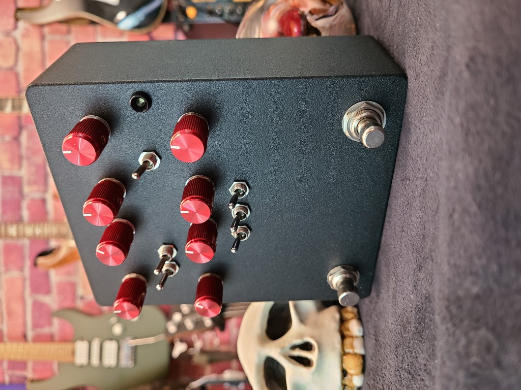
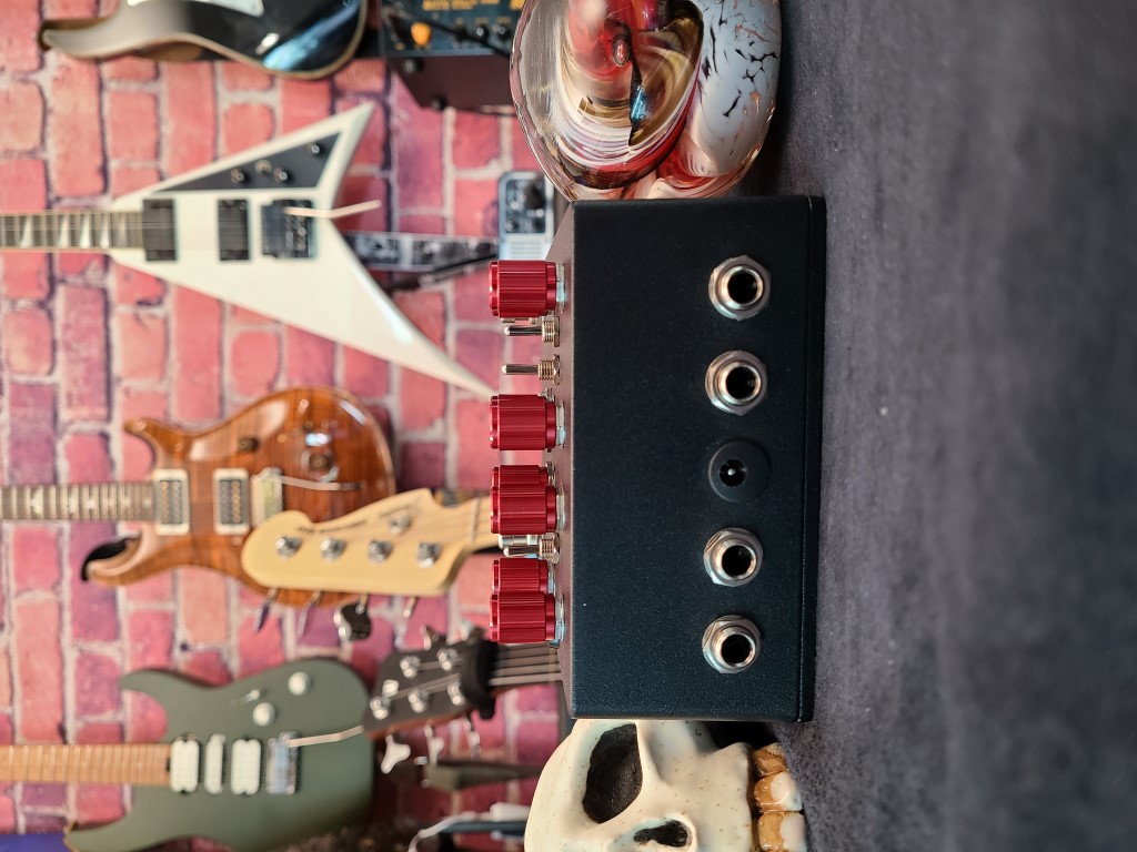
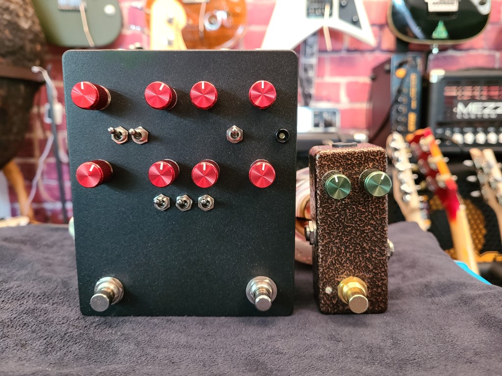
Another issue I have is the layout of controls, or at least the foot switches. There is just too much going on for it to fit in the 12590BB footprint. I used a 1590X which is a really deep 1590XX enclosure. It is HUGE. I think I am going to do some modification on it to try to create indicators for all the repeats. At least that it what I am telling myself I will do with all the extra room.
Controls
From the documentation:
The following are the standard external controls for this pedal:
- PREVOL — Controls the signal volume going into the buffer prior to the delay signal. Note that because the Sagan Delay is a buffered bypass effect, the PREVOL controls the guitar output volume even when the effect is off.
- MIX — Controls the amount of the “wet” delay signal volume being mixed back in with the dry input signal.
- DRYKILL — This switch toggles the dry signal path off, allowing only the wet (delay) signal to come through to the effect output. This allows for some fantastic ambient tones to come through. Note: If this switch is set to off then the dry signal path will be muted even when the effect is disengaged.
- FXPTH — This switch toggles the placement of the send/return effects loop in the Sagan’s delay signal path. The loop will be placed either:
- before the feedback loop (meaning that the first delay taps will be clean, and the delay signals that feed back into the delay lines will receive the effect)
- before the Mix control (meaning that the entire delay signal will receive the effect)
- DELAY — Controls the amount of time that the signal will be delayed after the clean signal and in between each “play head” (i.e., PT2399 chip).
- FDBK — Controls the amount of delay signal that feeds back into the delay lines after the initial echoes.
- TREBLE — Simulates the tape quality by controlling the high frequency response of the delay signal. If the delays start to sound piercing, consider reducing the Treble.
- BASS — Simulates the tape quality by controlling the low frequency response of the delay signal. If the delays start to sound muddy and undefined, consider reducing the Bass.
- TRI/OFF/SQR — Toggles between different waveforms of the LFO. You have options for a triangle wave and a square wave, or you can simply switch off the LFO modulation.
- RATE — Controls the LFO speed.
- DEPTH — Controls the LFO depth.
- 1/2/3 TOGGLES — These toggle switches turn on/off the path for each of the three delay paths.
The circuit also includes two internal trimmer controls, which could be technically externalized if you wish to drill a small hole in the face of the pedal enclosure:
- SAT — Short for “Saturation,” this controls the amount of input signal which saturates the simulated tape line.
- SWAY — This controls the swing of the LFO modulating the delay time. When fully CCW, the wave should peak quickly and descend slowly; fully CW, the wave should take longer to ramp up and descends quickly. Positioning the trimmer at 12:00 produces a more or less balanced waveform
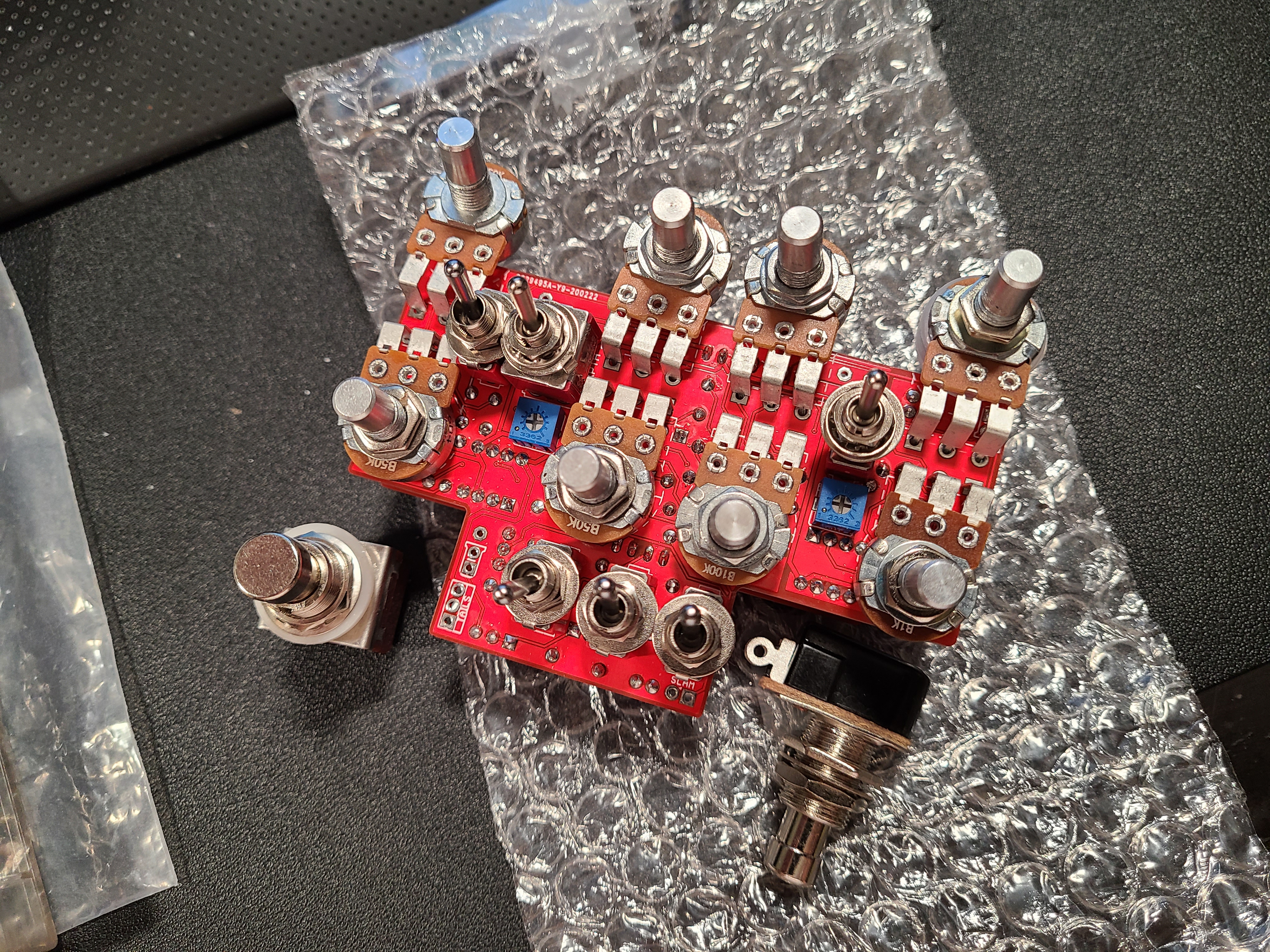
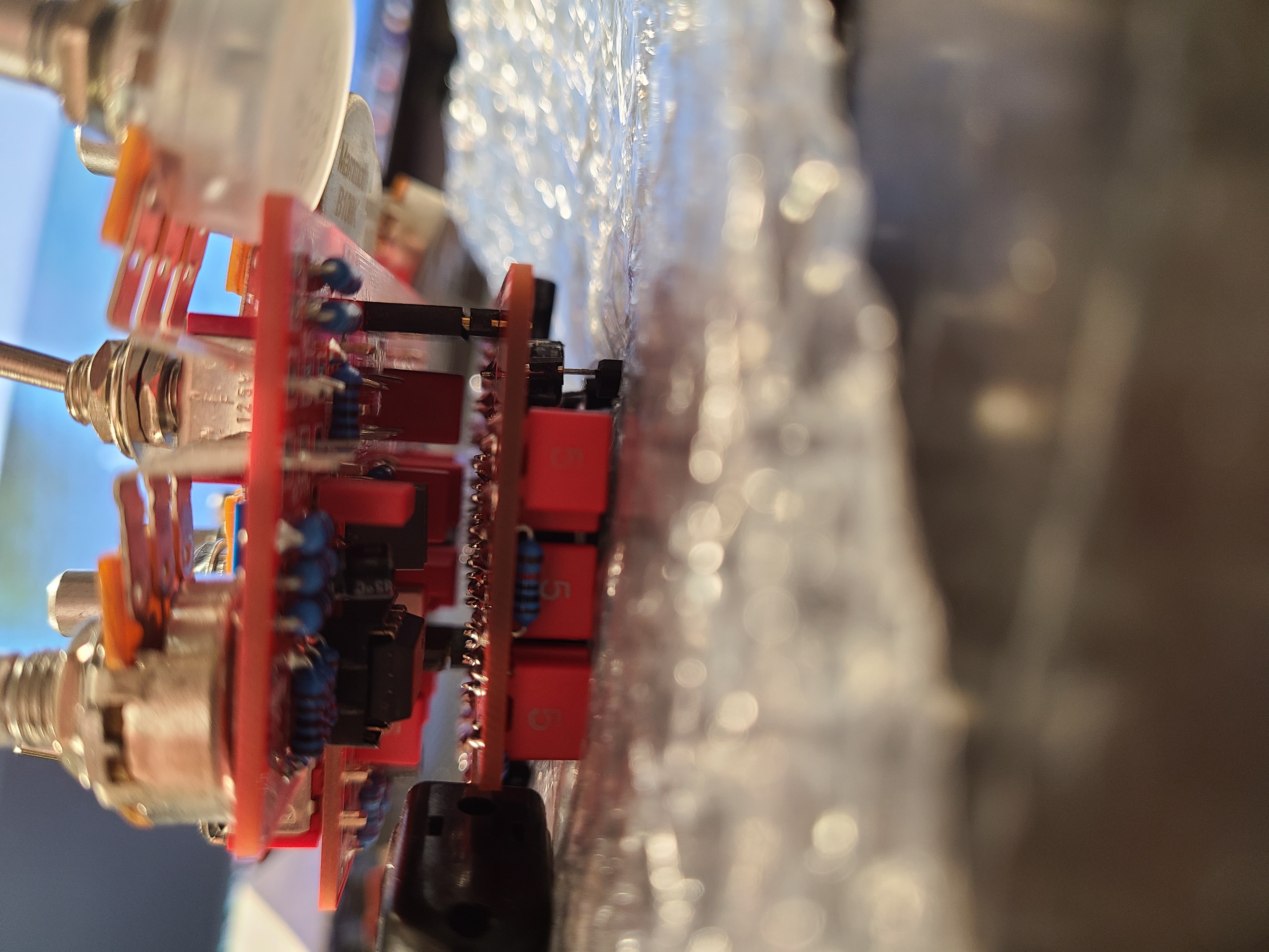
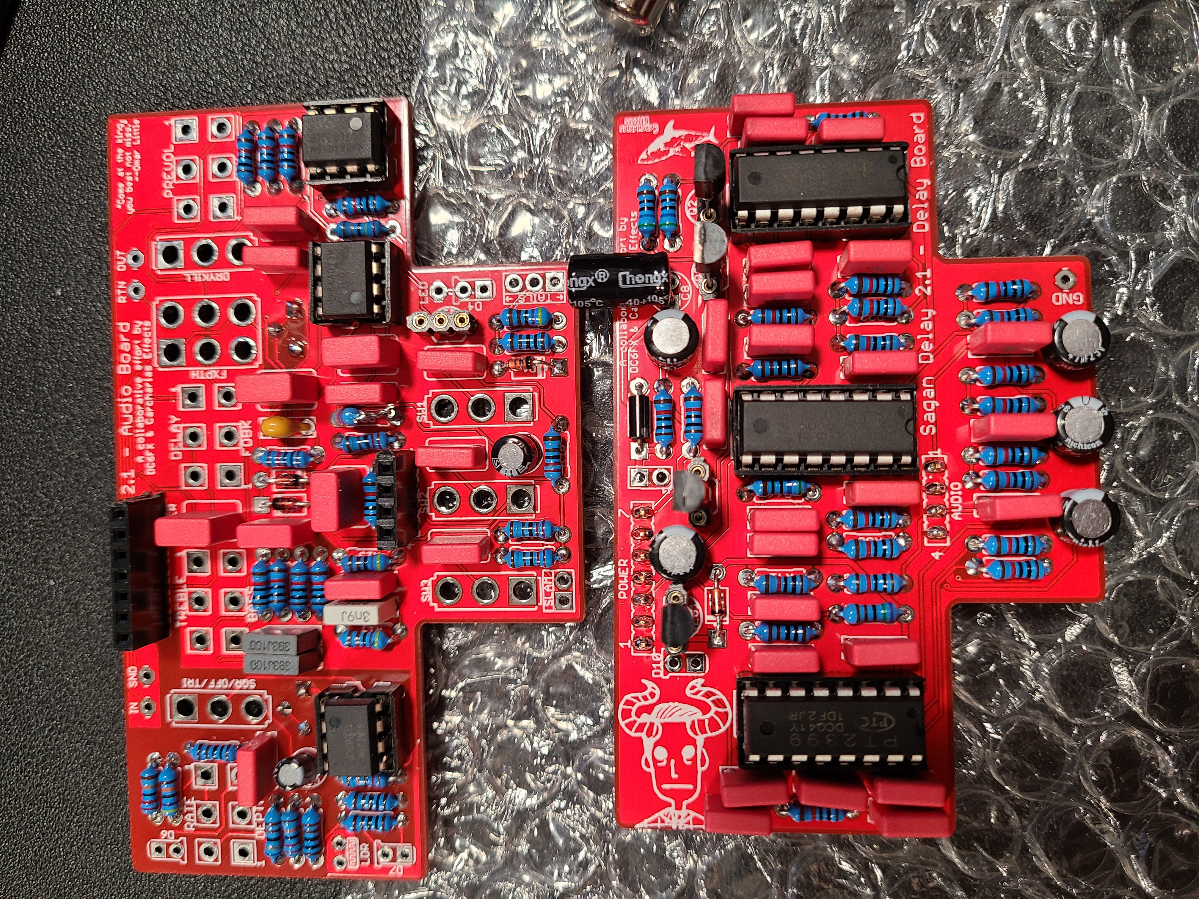
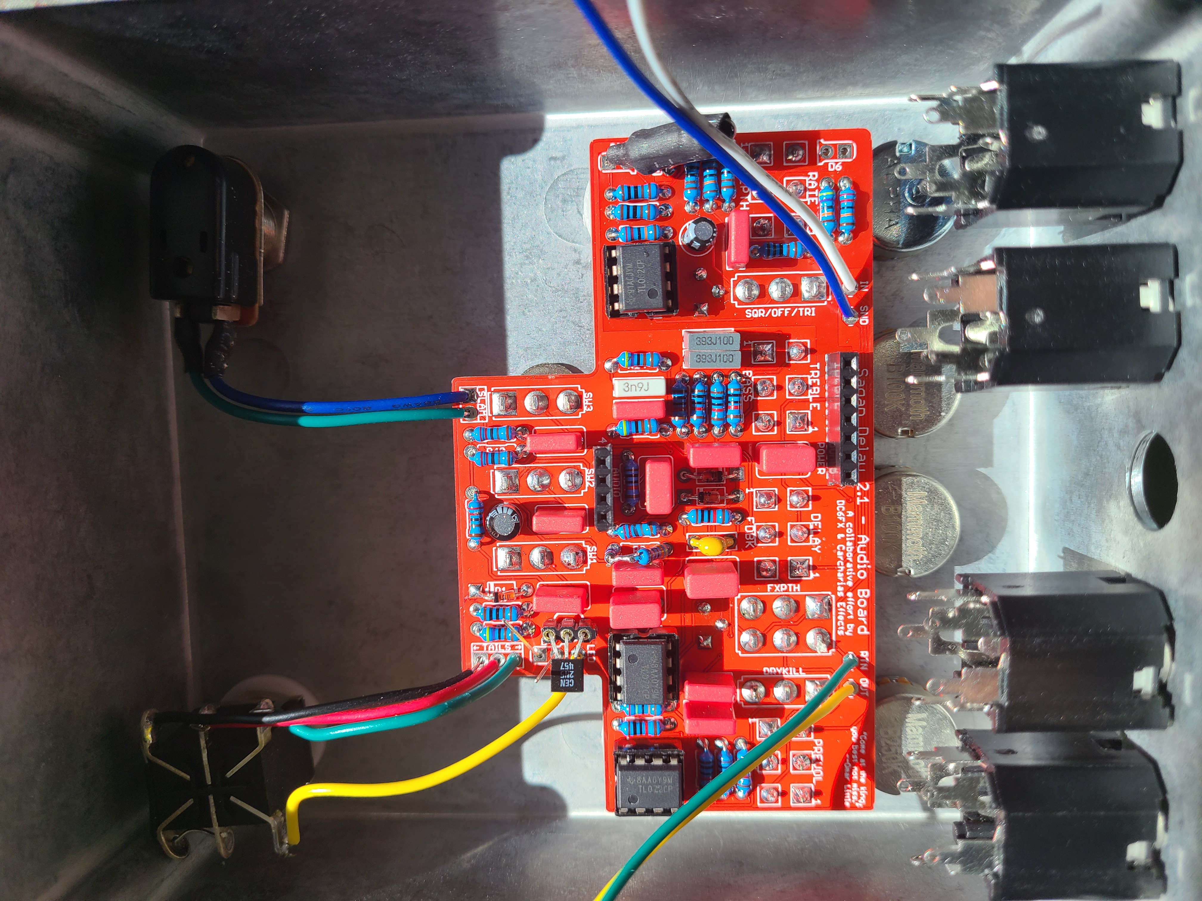
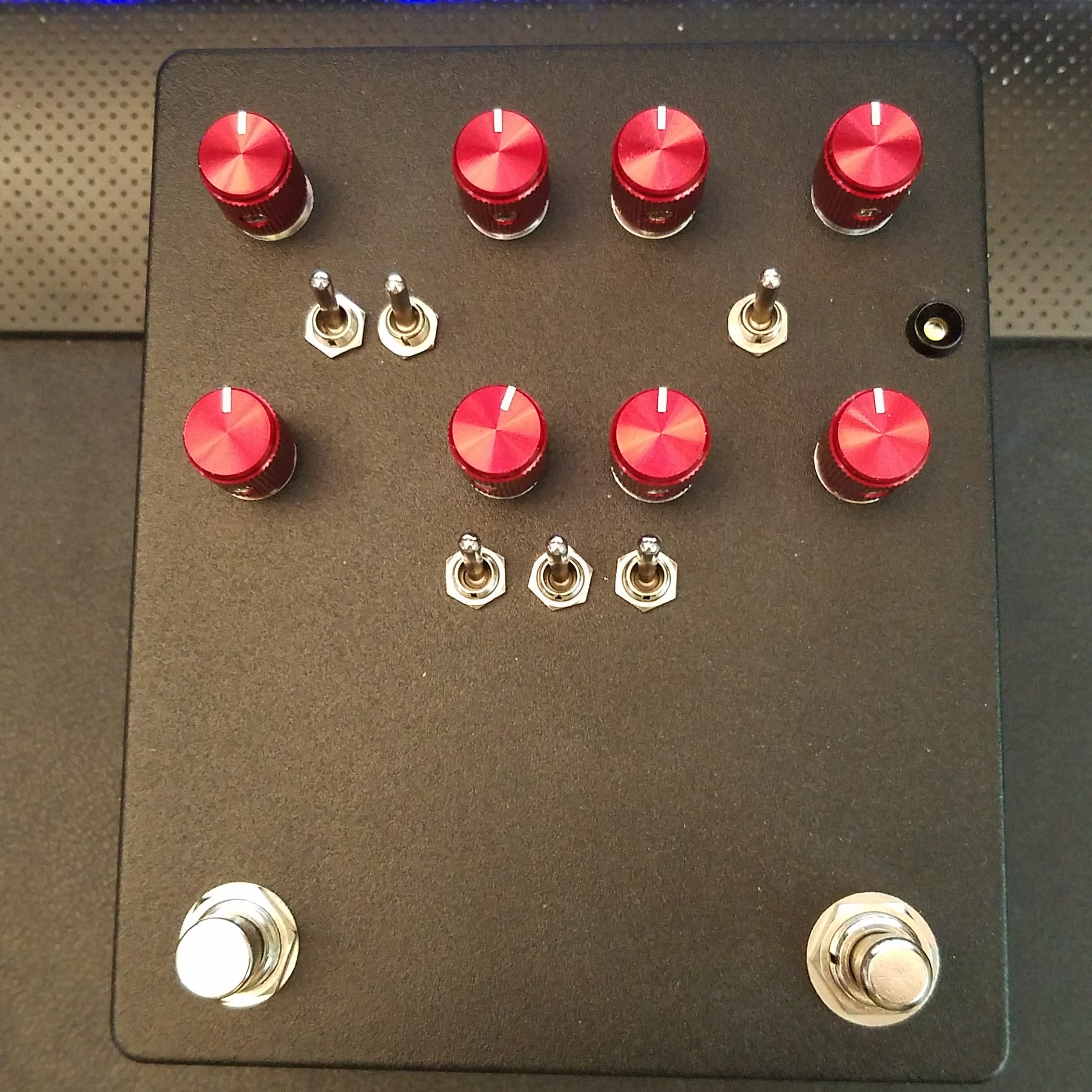
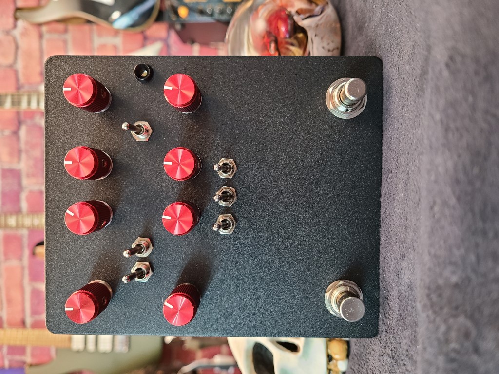
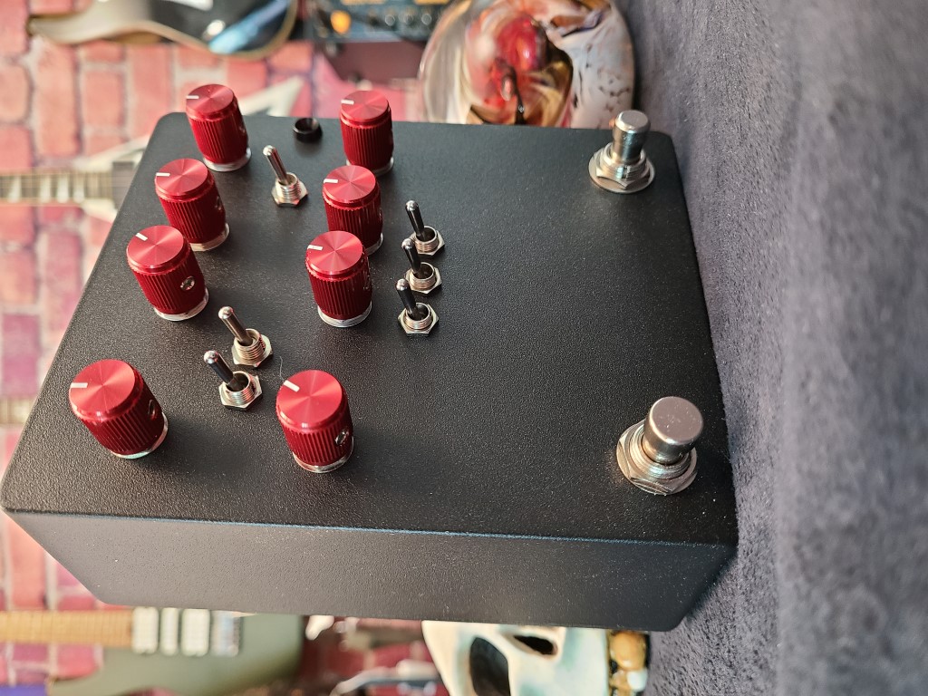
Build Gallery