After reading a lot of forums and building pedals for a few months I wanted to have a test rig. I had used a makeshift audio probe (alligator with 100nF cap connected to output tip) and I felt it was time to get something a little more usable. One of the problems I was having was trying to play while probing. Let me tell you. I cannot probe and play at the same time. So I decided I would put a few designs together and build myself a test box. This is the story of how it went.
Breadboard
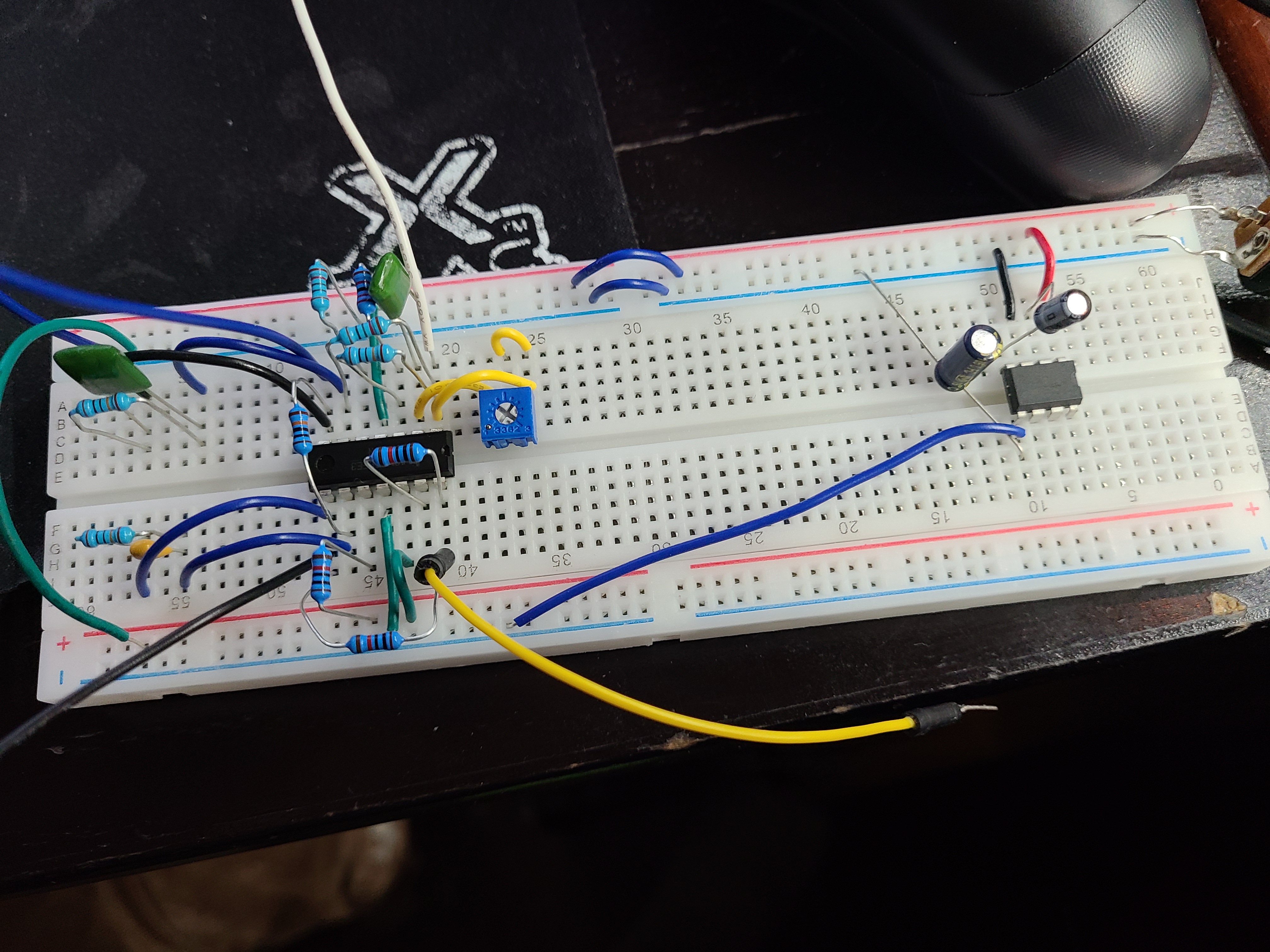
I breadboarded the schematics found I online for LM324 wave generator. I was originally trying to create the circuit here. But was having problems and found this a little easier to follow, on the right is the voltage inverter I got from here.
Schematics
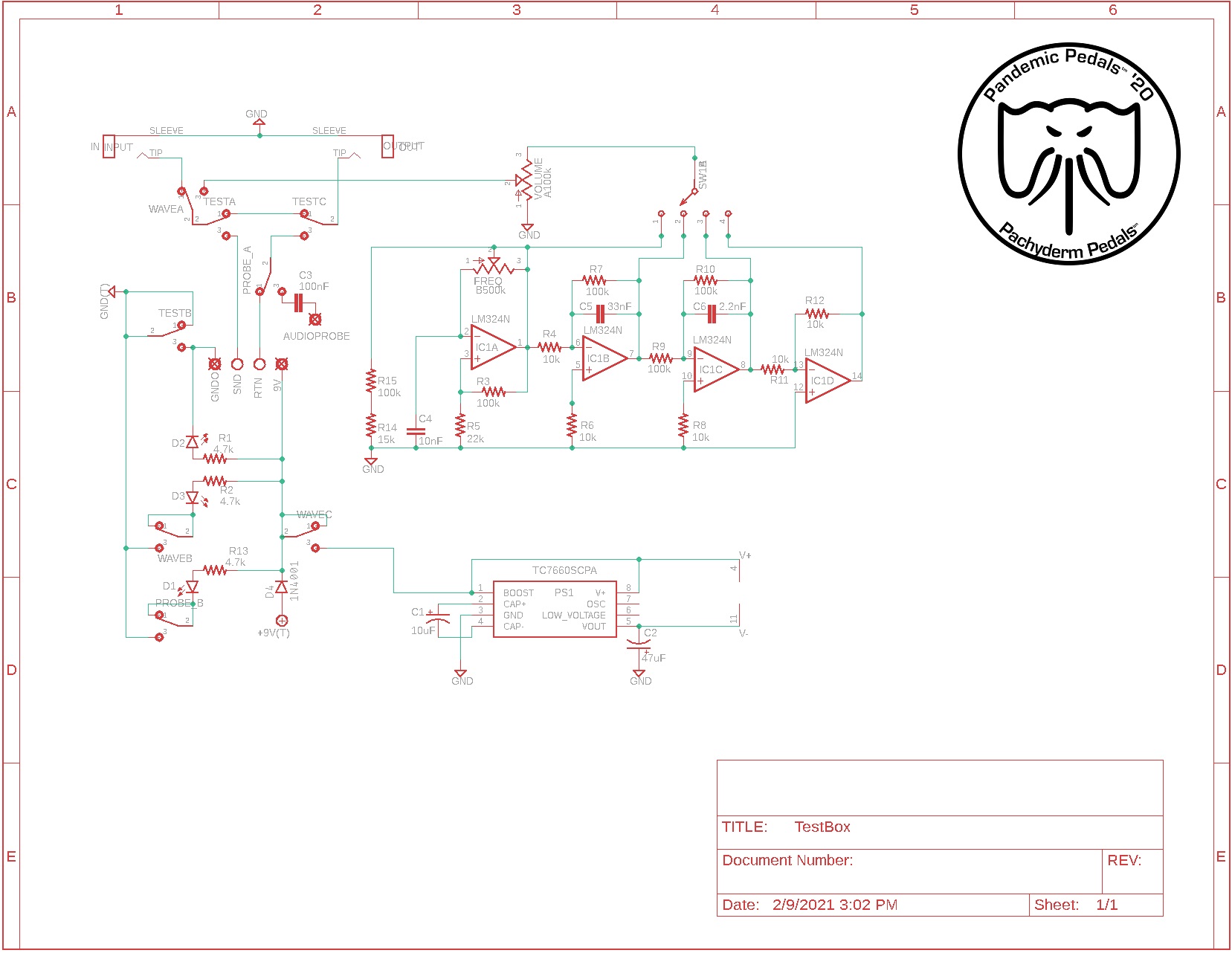
I then built a schematic of what I wanted to build in Eagle. This is the schematic of what is in the box at this time. I believe I need better power handling and I think I have some grounding issues. Sometimes I get noise when in bypass, but I think it may also have to do with how I hook the test circuit ground up to the test box. I would also like to improve the waves and have a lease a trim pot to adjust output.
Stripboard Layout
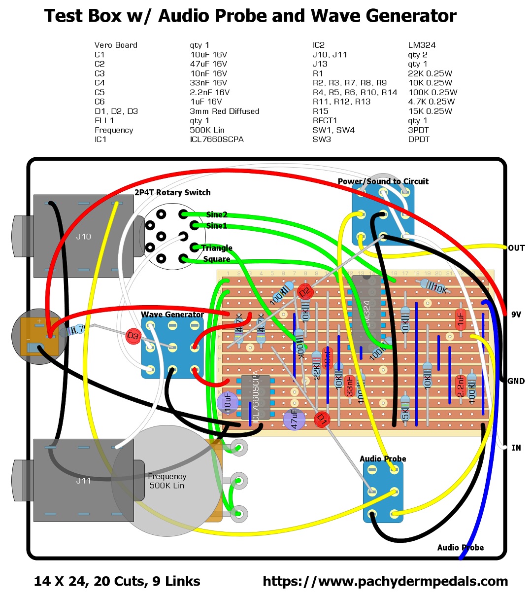
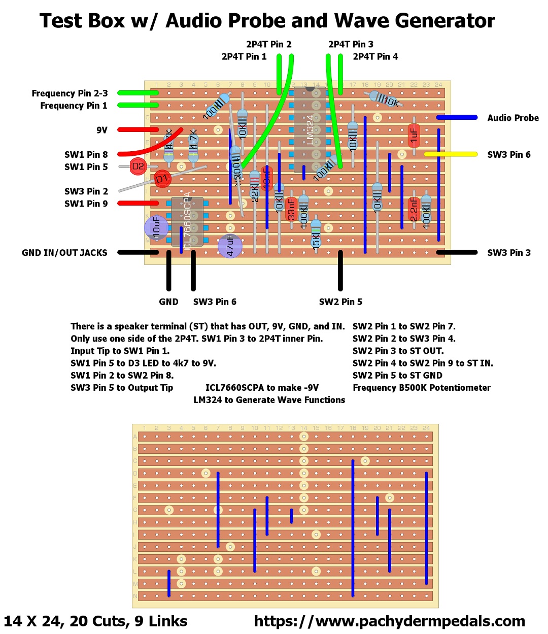
I then created a layout of what I was planned to build using DIYLC. This is the layout in the box. Done in DIYLC 2. It can be had here. I know there is a newer version but every time I go to download I get warnings.
The first layout follows what I was used to seeing on Tagboard Effects. It lets me see the back and front to I know where the cuts and jumpers are. Really hoping to get batter at using all these tools in the future.
Building the Board
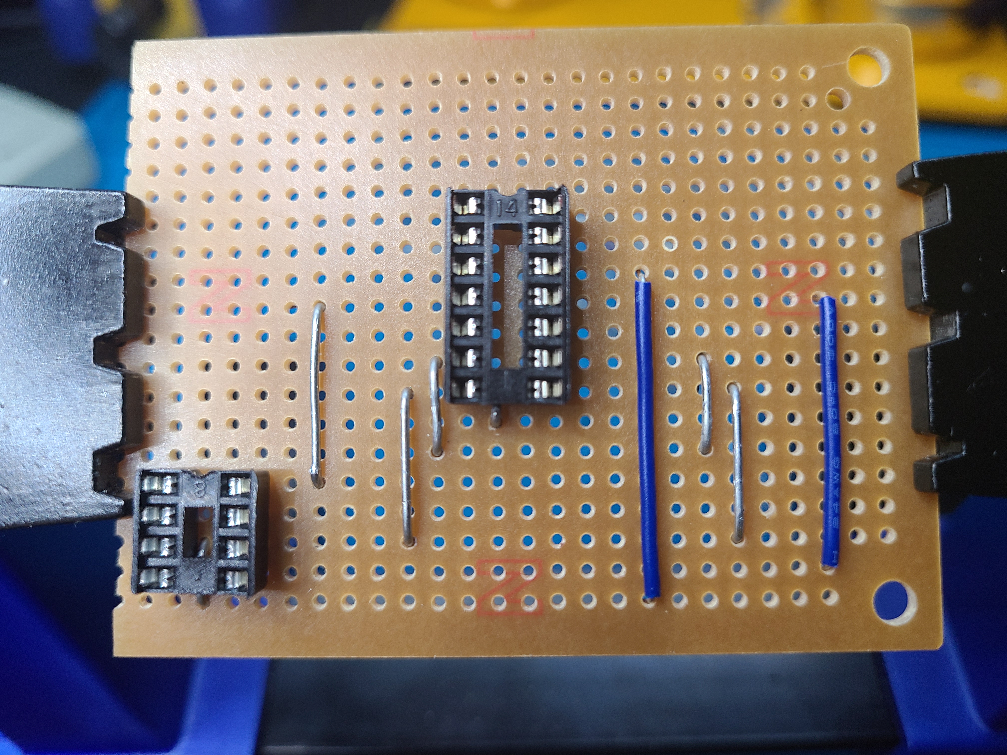
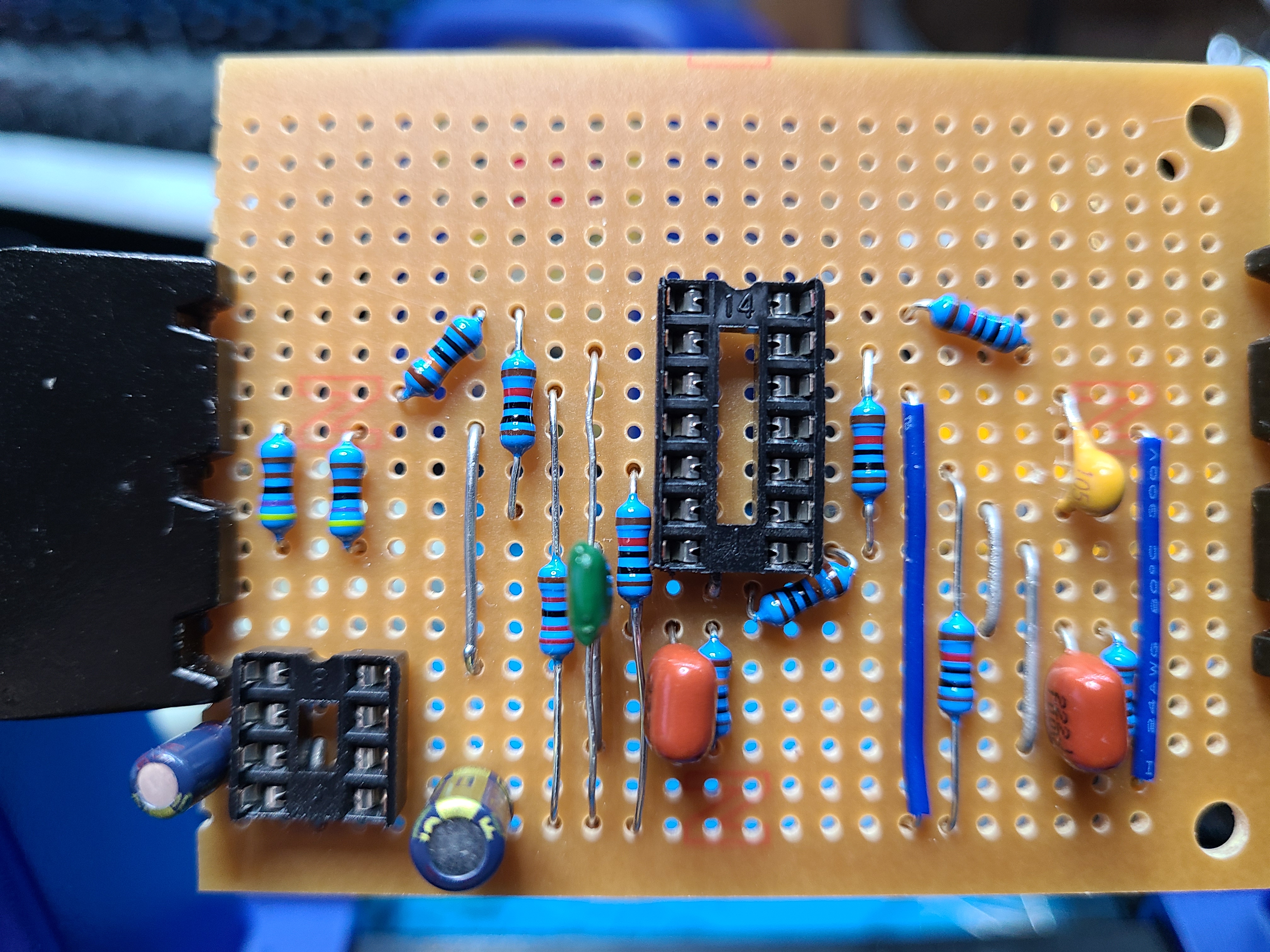
Step 1: Install the jumpers and sockets. This helps me better location the positions on the board for the cuts.
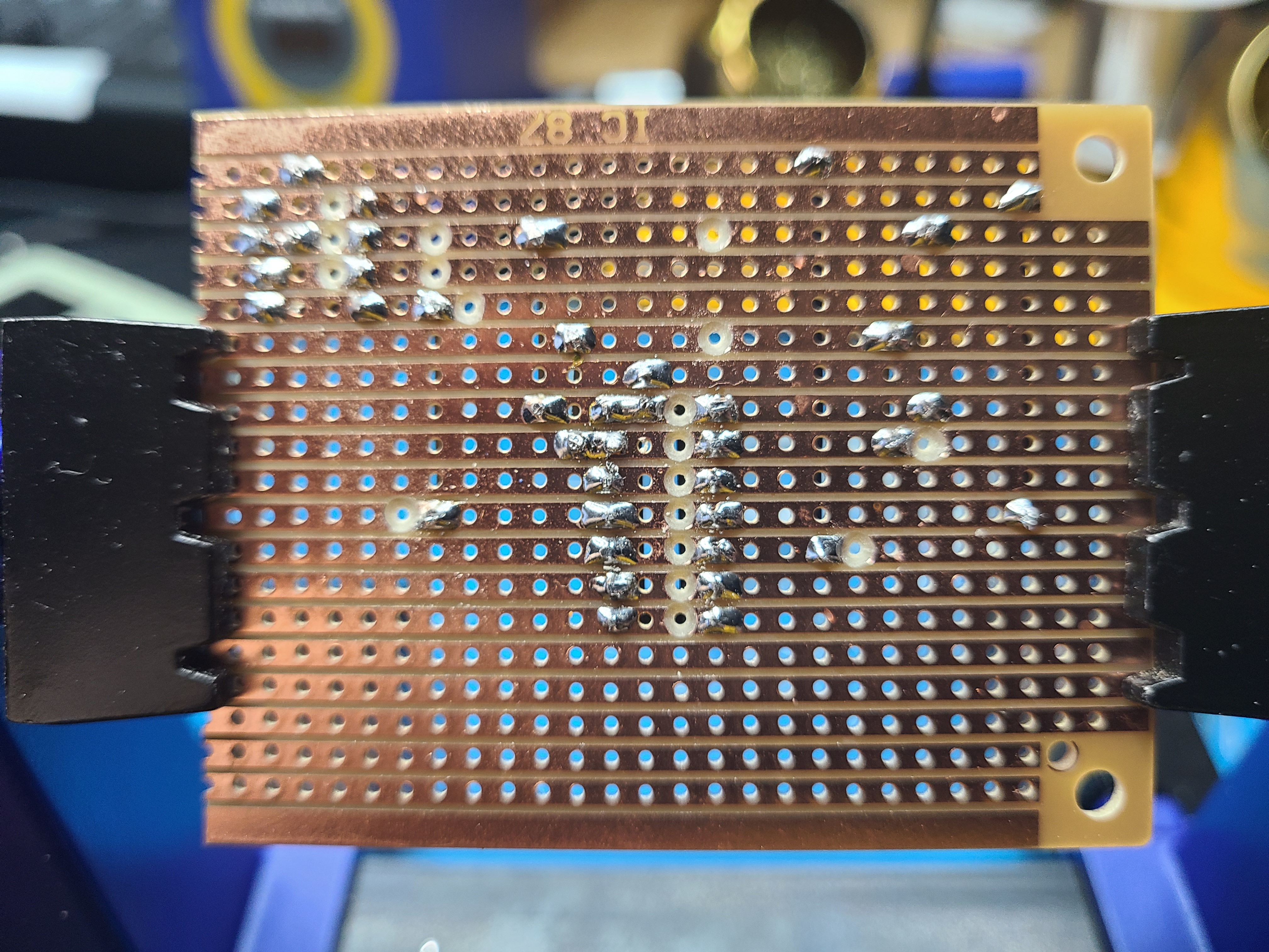
Step 2: Make the cuts. I did this by hand by twisting a 3/16 drill bit between my fingers.
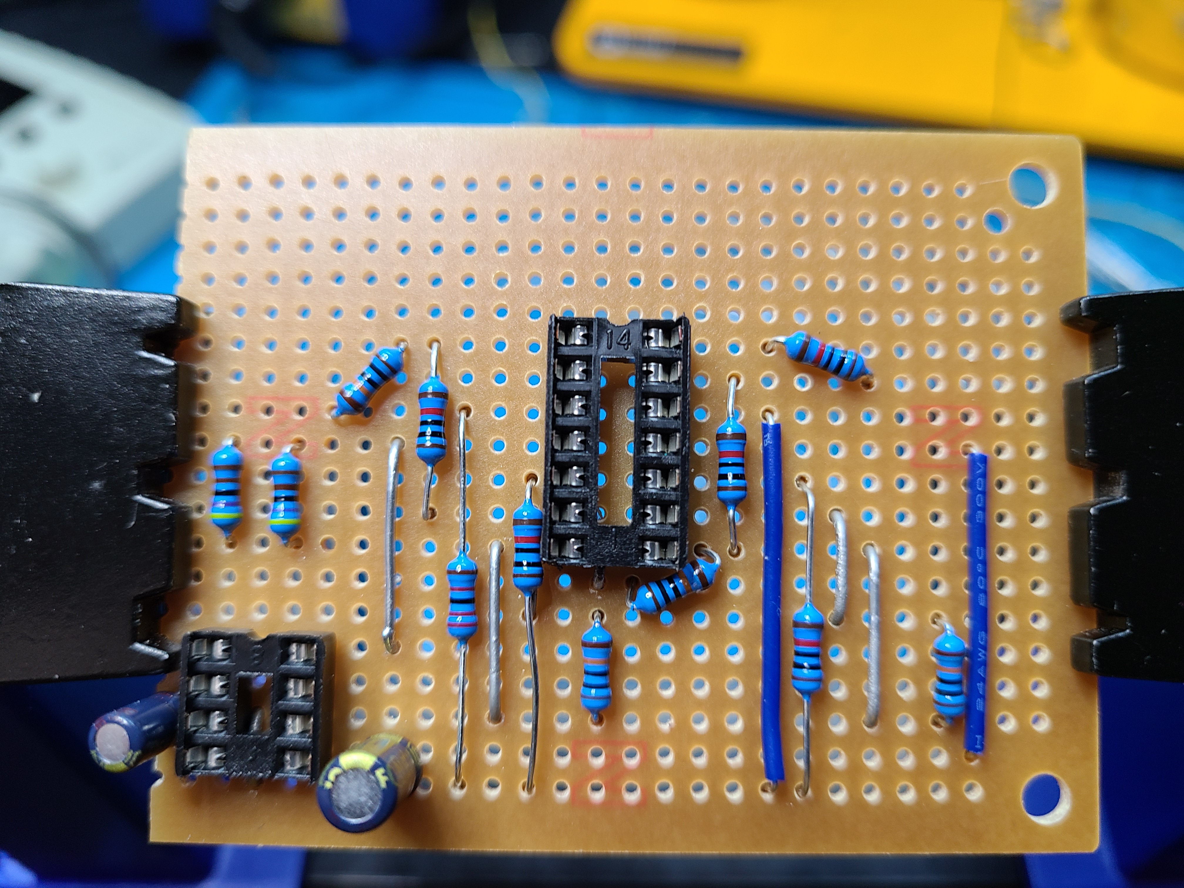
Step 3: Install resistors on the board.
Step 4: Install capacitors.
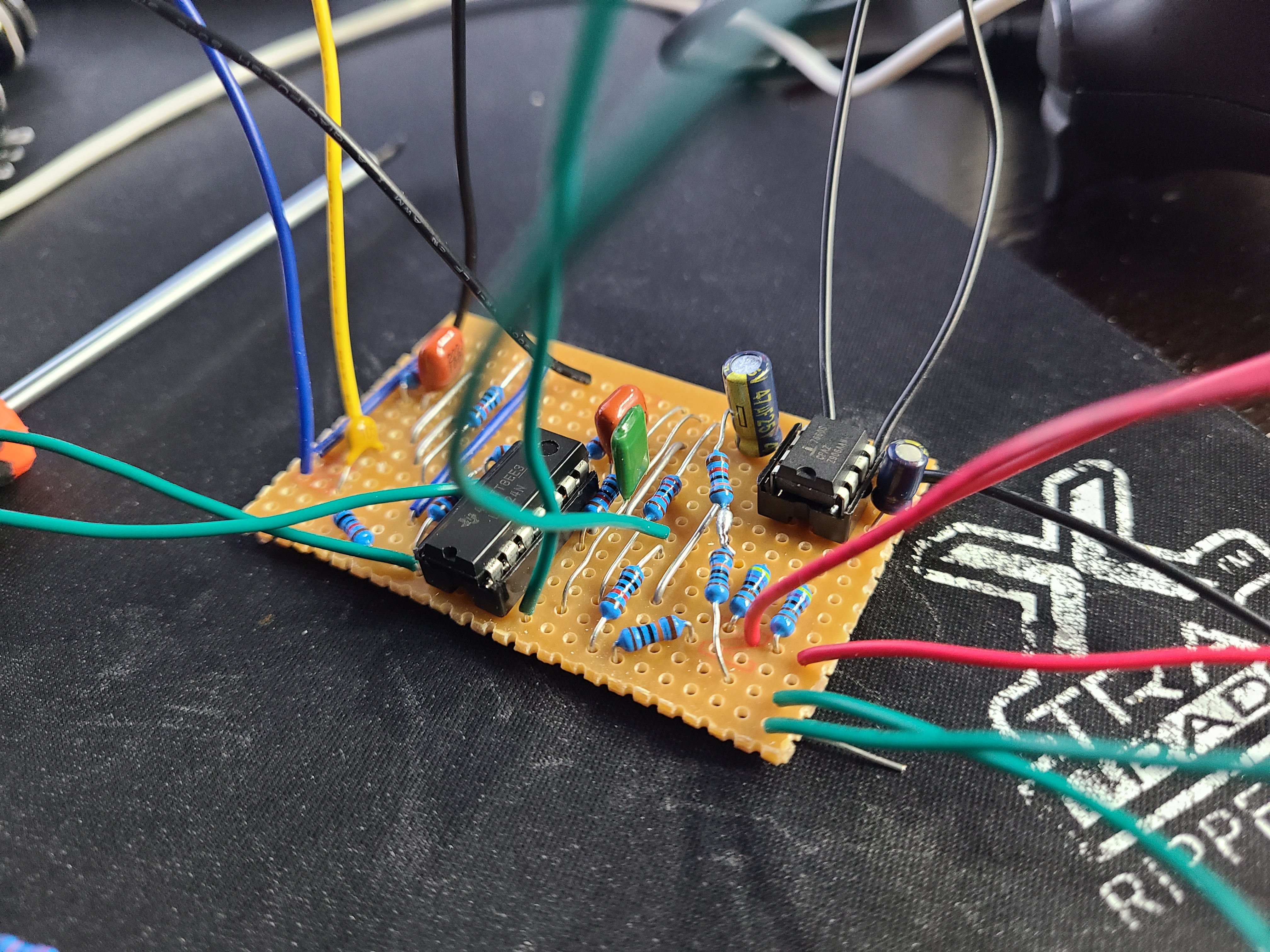
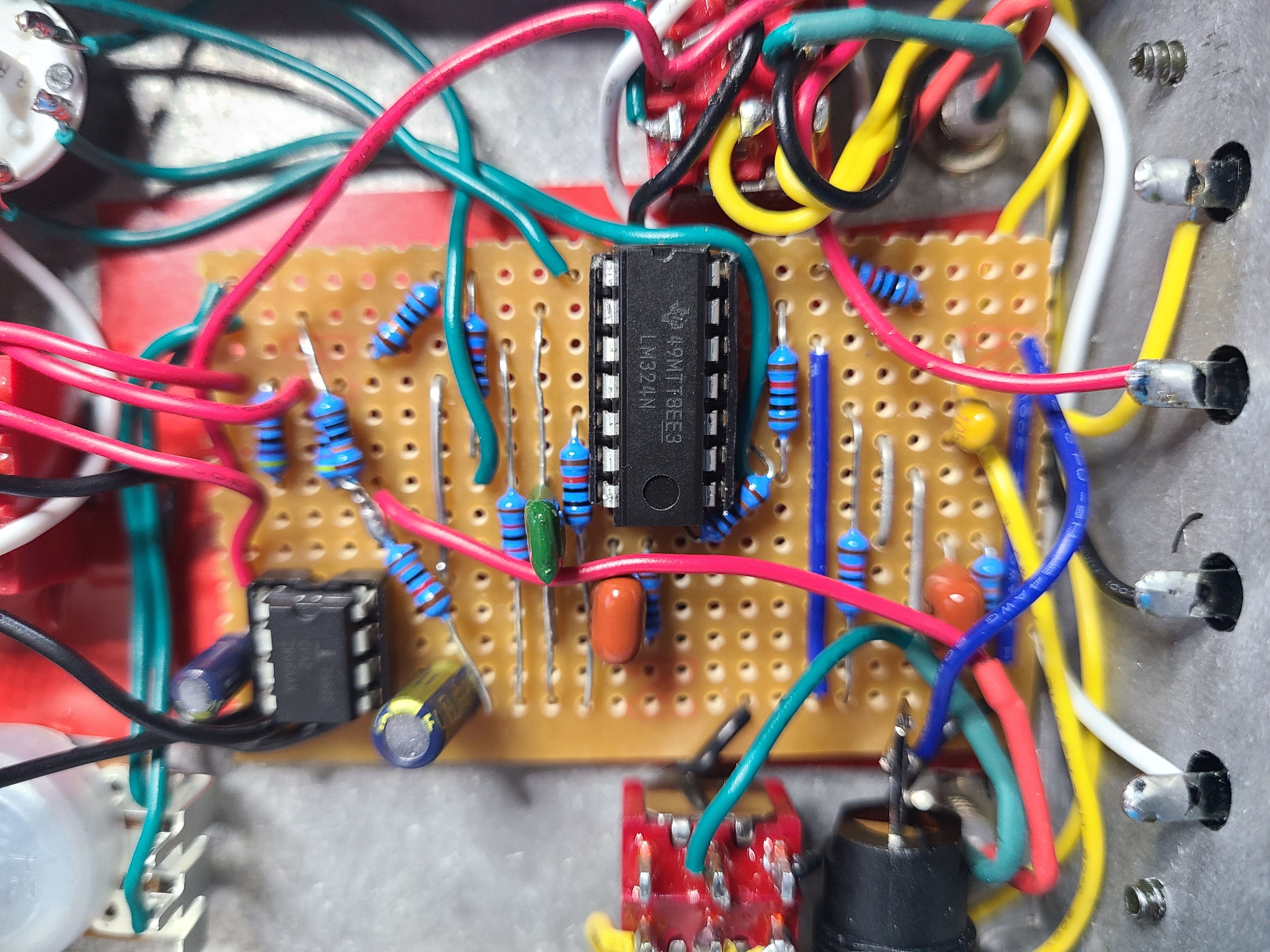
Step 5: Install wiring and ICs.
This is the point at which I would get power to the board and test that everything was working. I of course did not do that. That is why I did not know how bad the volume would be and I could not make changes. Well actually I did not want to unsolder the components when I did find out. I figure this is a beta and i would learn.
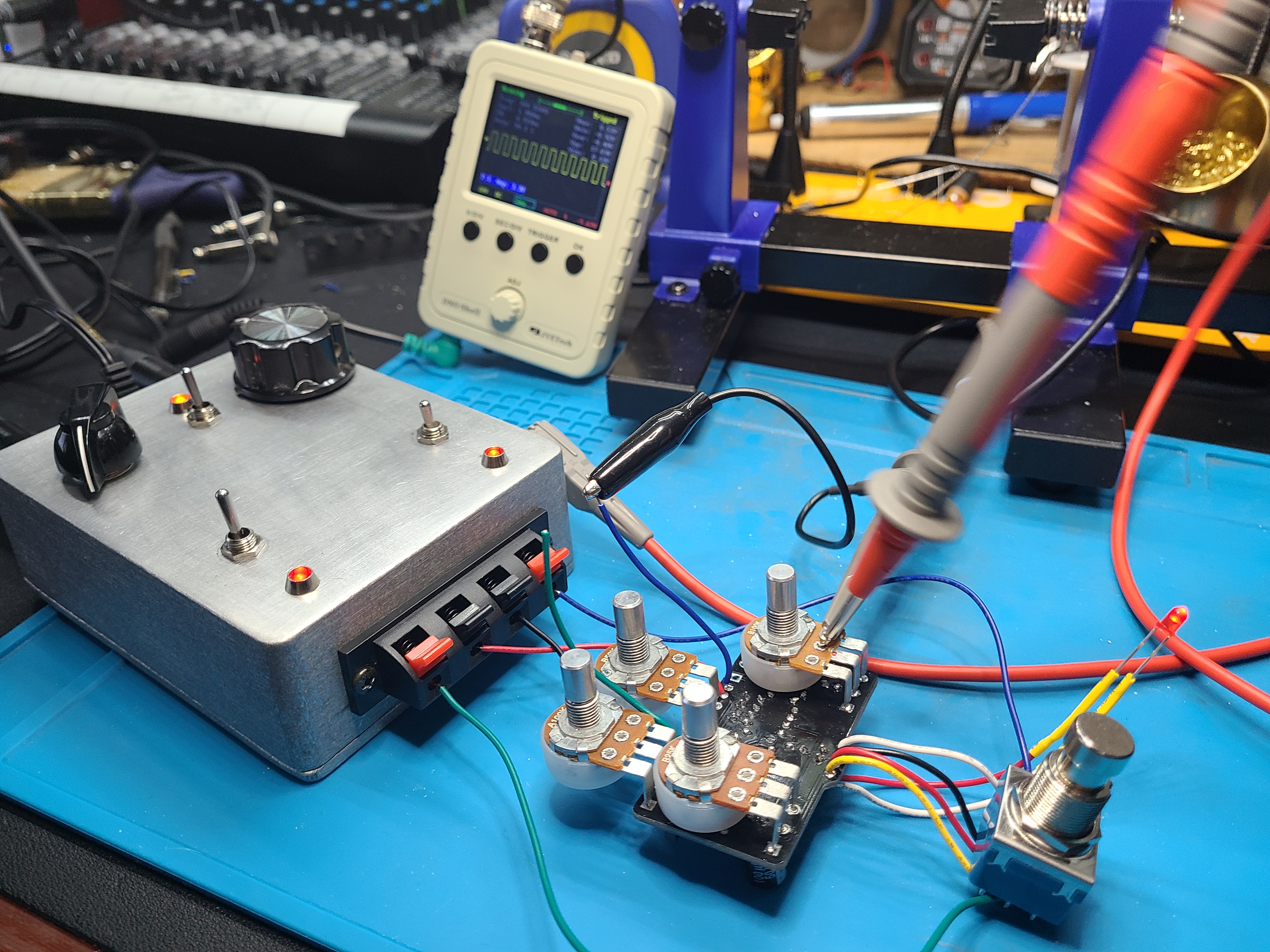
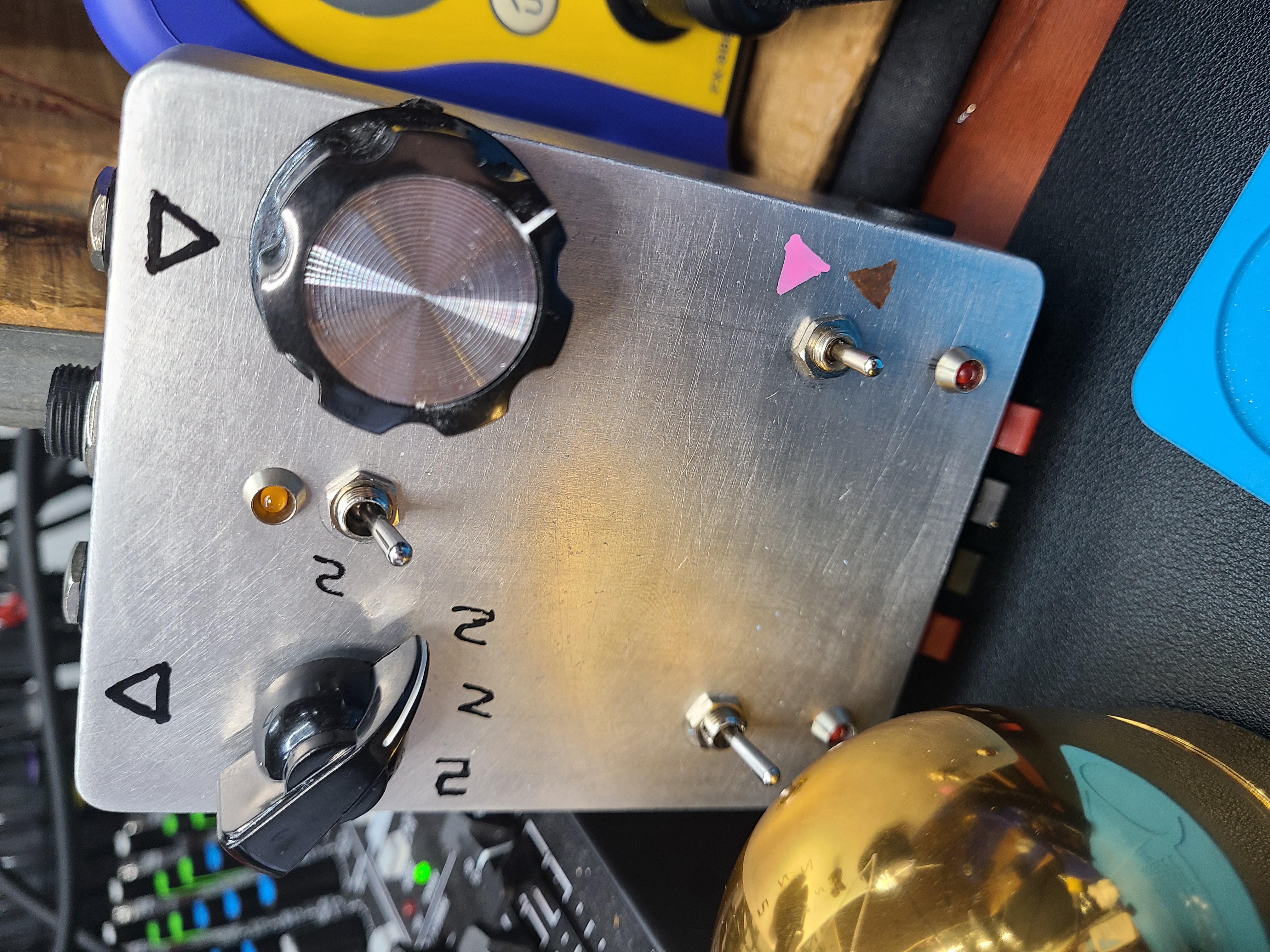
Install in Enclosure
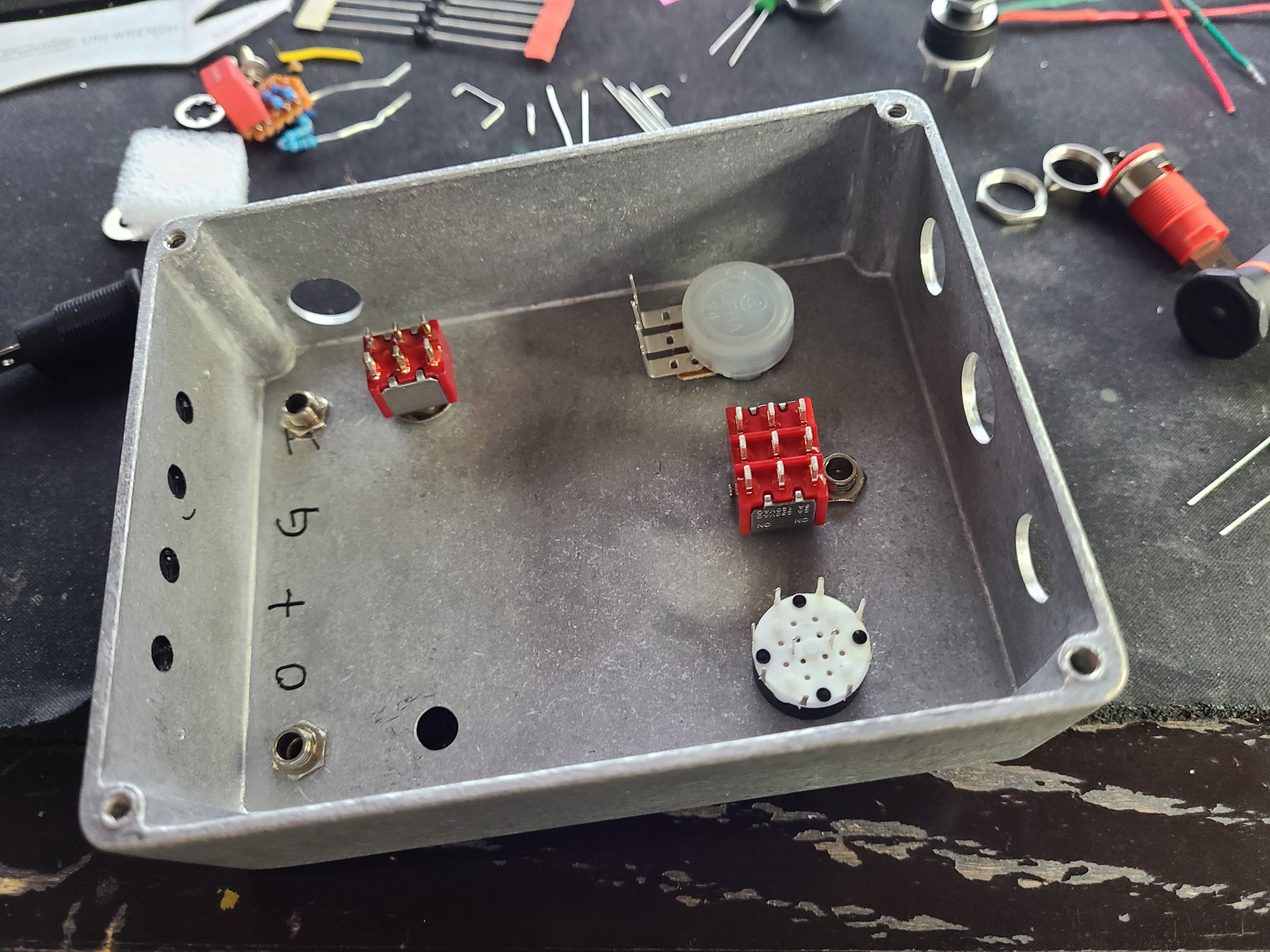
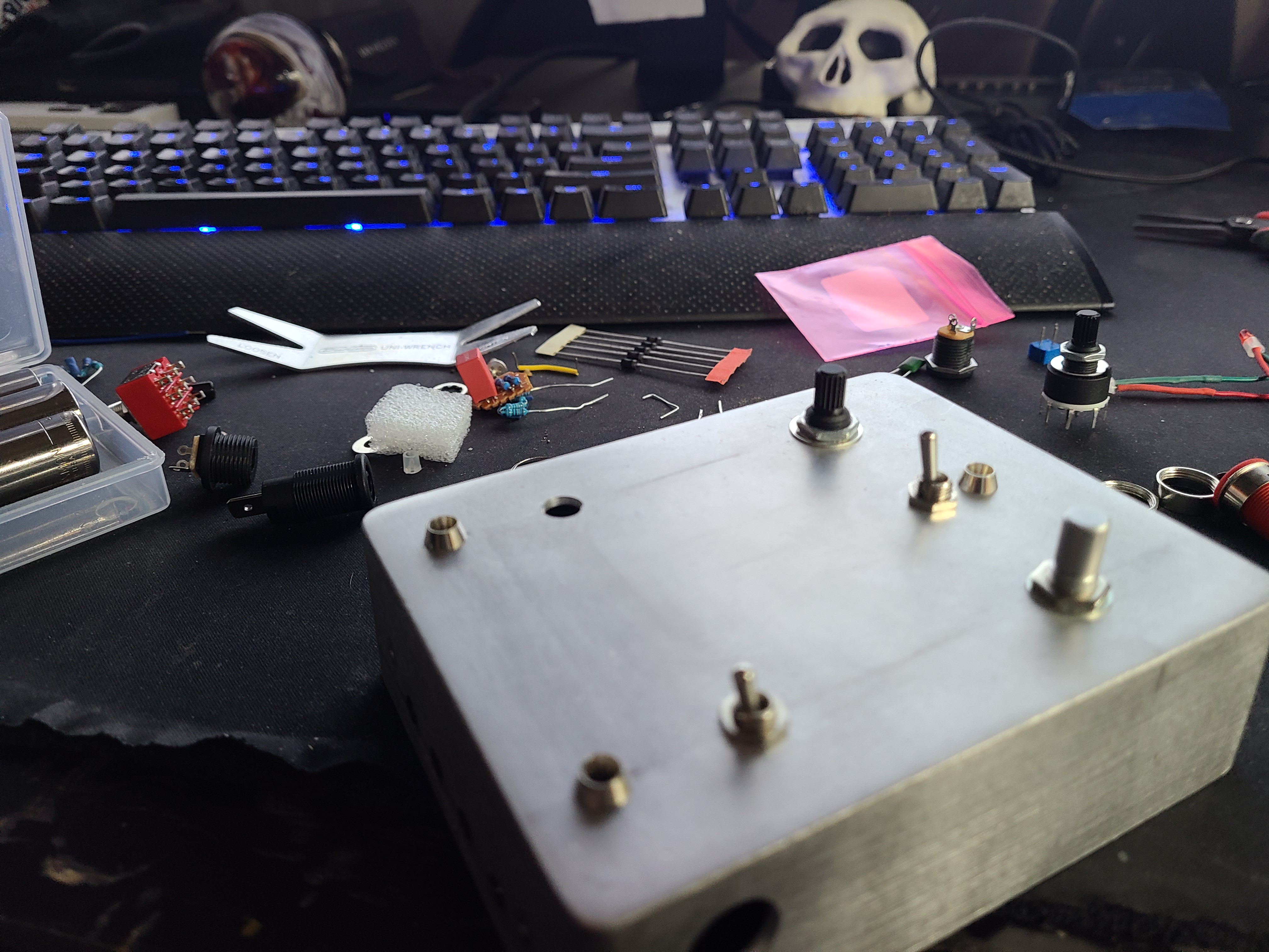
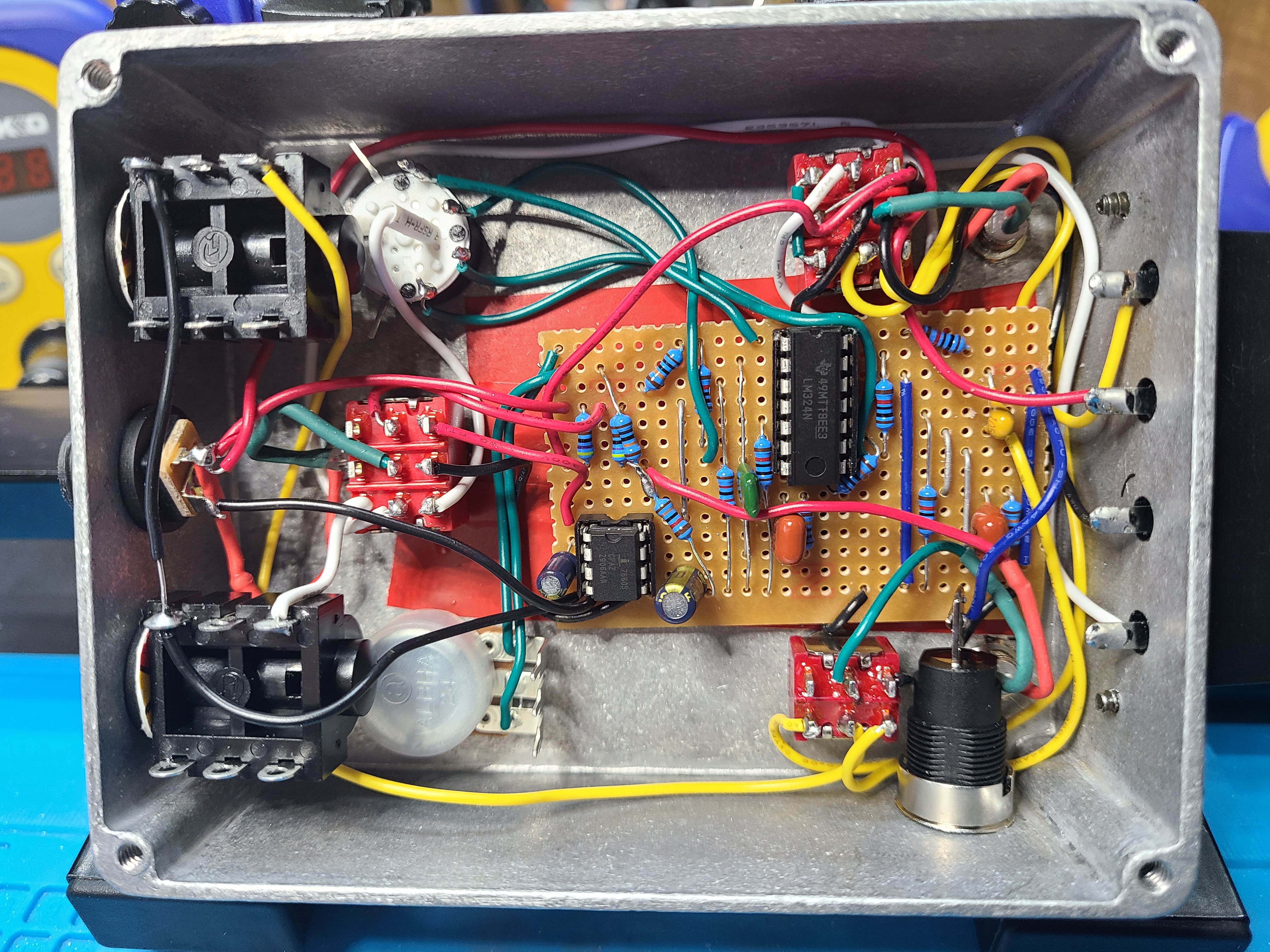
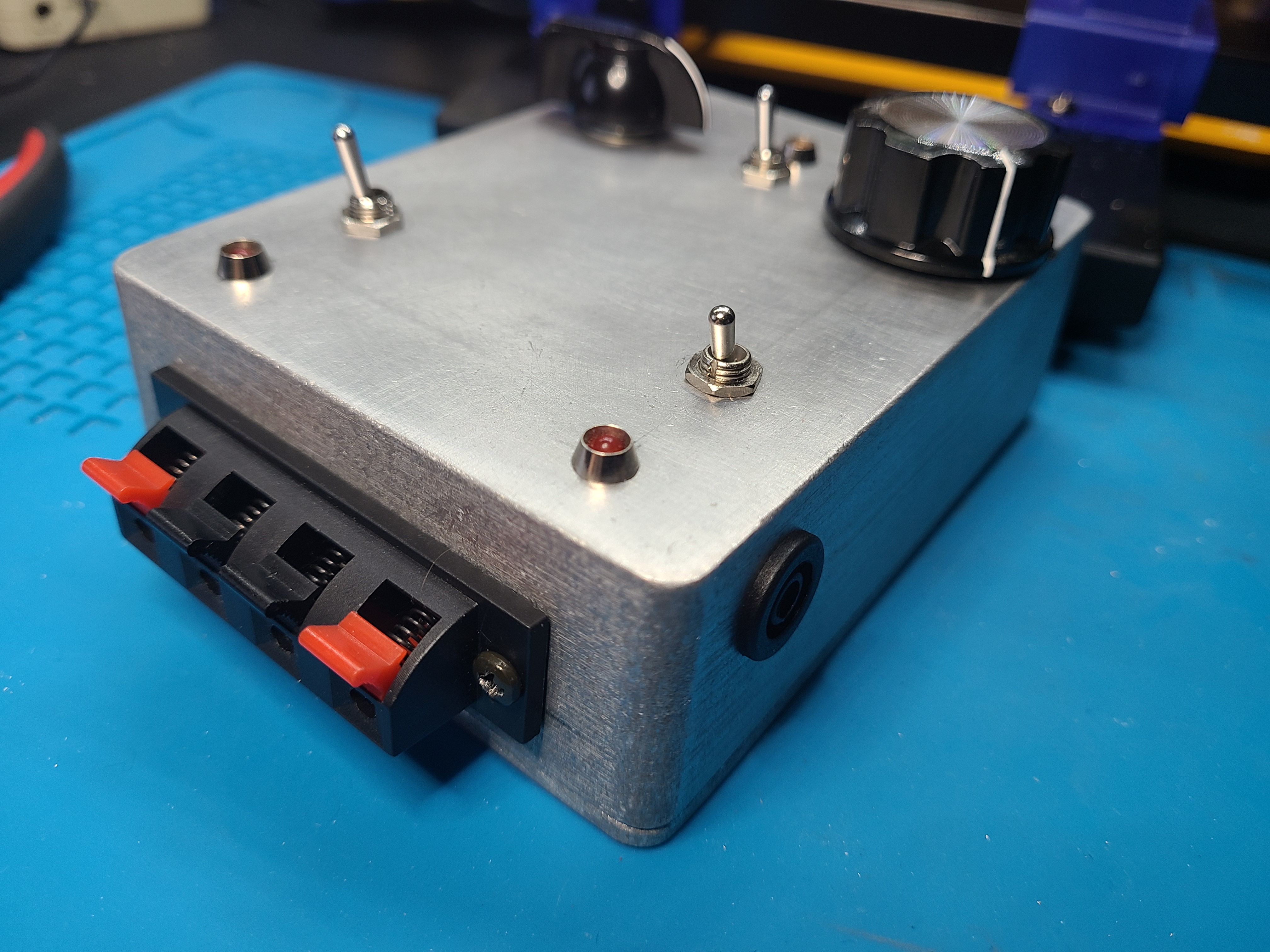
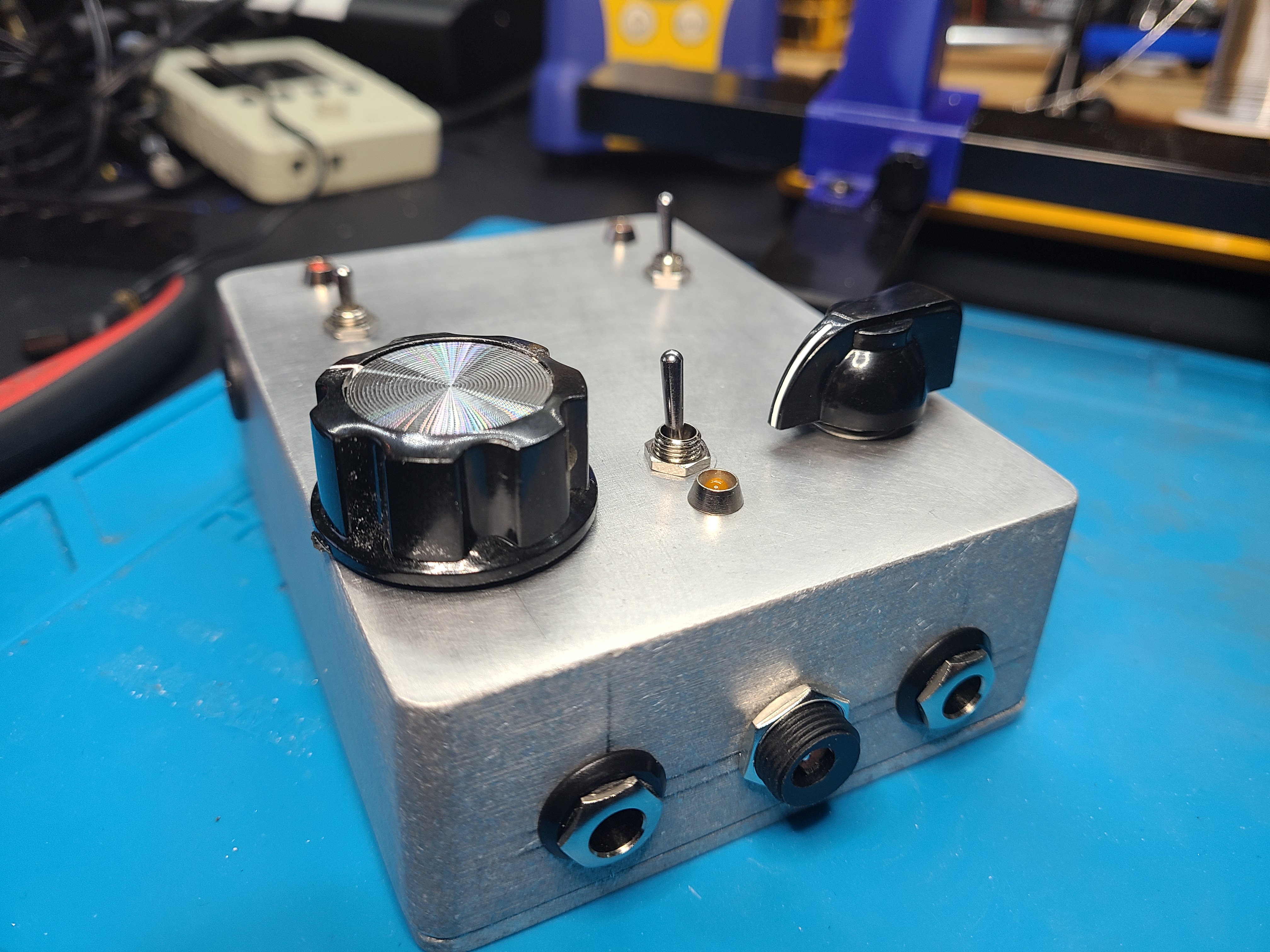
It was now time to drill holes (A tutorial for another day). Install components, and get the board in.
Look at all the spaghetti. I had to be careful not to let the wires touch that are routed over each other. It’s my first board. I will get better with time.
The layout is easy to use. I got the banana clip socket from amazon. They take the leads that came with my DMM really well.
Conclusion
I am extremely happy with the way this turned out. I will need to perfect my skills with the perf board. I think I am going to make a PCB for this over the nect year. It coould also do with a volume control. The frequency generator is LOUD. I can hear it through my headphones.
Video